Table Of Content
The notation includes attribute types (e.g., int, Token, etc.), method parameters and return types, and default values for attributes. Want to create a class diagram to document your system, but short on time? The name of the class is only needed in the graphical representation of the class. A class is the blueprint of an object which can share the same relationships, attributes, operations, & semantics. The class is rendered as a rectangle, including its name, attributes, and operations in sperate compartments.
What Are UML Class Diagrams?
A class diagram describes the structure of an object-oriented system by showing the classes in that system and the relationships between the classes. A class diagram also shows constraints, and attributes of classes. If you're new at creating UML diagrams, your best bet is to use a pre-designed template with all the model shapes and notation options. Miro has a UML class diagram template that works as a base for any UML class diagram you need to make. Basic notation in a UML class diagram includes the labels in the class members, their visibility (who can access them), and the eventual packages. When creating a UML class model, use the web app-approved font, Open Sans.
UML Class Diagram
When you select a line, click the line icon to edit its properties. Inheritance refers to a relationship between a parent class and a subclass that serves as an extension of it. This is represented by an arrow with an open head pointing toward the parent class from the subclass.
Visibility of Class attributes and Operations
A class can have its objects or may inherit from other classes. A Class in UML diagram is a blueprint used to create an object or set of objects. It is a template to create various objects and implement their behavior in the system. A Class in UML is represented by a rectangle that includes rows with class names, attributes, and operations.
It’s easy to edit your Mermaid diagram after creating it — just double click on it and you will re-enter the editing modal and can change the text as necessary. Associations are lines between classes that indicate some kind of connection between them. A system in a UML Use Case Diagram is a rectangle spanning all the use cases in the system that defines the scope of your system. Anything within the box represents functionality that is in scope and...
Overview of the JAD Methodology
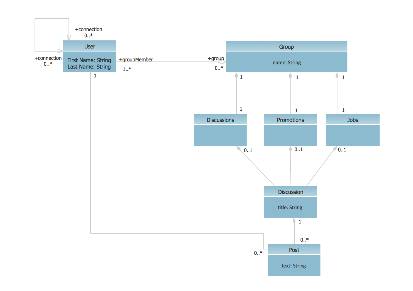
The class diagram example below shows a set of classes related to flight management. A generalization is a relationship between a general thing (called the superclass) and a more specific kind of that thing (called the subclass). Generalization is sometimes called an "is a kind of" relationship and is established through the process of inheritance. Place multiplicity notations near the ends of an association. These symbols indicate the number of instances of one class linked to one instance of the other class. For example, one company will have one or more employees, but each employee works for one company only.

How to Create a Class Diagram on Creately with Your Team?
Our Microsoft integrations allow you to import your diagrams seamlessly after you collaborate in real time within the cloud. Continue to add class shapes until your static application is fully represented. First, add the class names and link them with the appropriate connectors. You can add attributes and functions/ methods/ operations later.

Interactions
With our UML diagramming software, creating these diagrams is not as overwhelming as it might appear. This guide will show you how to understand, plan, and create your own class diagrams. UML class diagrams are used to illustrate the structure of a computer program.
Directed Association
In the model, the class name section is the only mandatory section in a class. The other two are optional, depending on the diagram's objective and view. The class notation without the last two compartments is called a simple class and it only contains the name of the class.
Class diagrams are used throughout process modeling which can be done with Unified Modeling Language (UML) software. The +, -, # and ~ symbols before an attribute and operation name in a class denote the visibility of the attribute and operation. You've learned what a Class Diagram is and how to draw a Class Diagram. Get Visual Paradigm Community Edition, a free UML software, and create your own Class Diagram with the free Class Diagram tool.
Association specifies a "has-a" or "whole/part" relationship between two classes. In an association relationship, an object of the whole class has objects of part class as instance data. A realization relationship connects a class that realizes or implements the behavior defined by another. The models in this relationship are called the supplier and client elements or superclass and subclass. The supplier is the source, and the client is the specification element. Realization notation is visualized with a staggered line and a hollow triangle shape.
They're made up of a straight line that loops alongside the class model. Their purpose is to visualize a relationship between one class instance and another instance of the same class. Open the Themes feature in the right sidebar to select a pre-made style format, or select your specific shapes and lines of choice to update their fonts, colors, and line settings. There are several class diagram notations that are used when drawing UML class diagrams.


No comments:
Post a Comment